Checking parts of the K-Jetronic injection system - Audi 80.
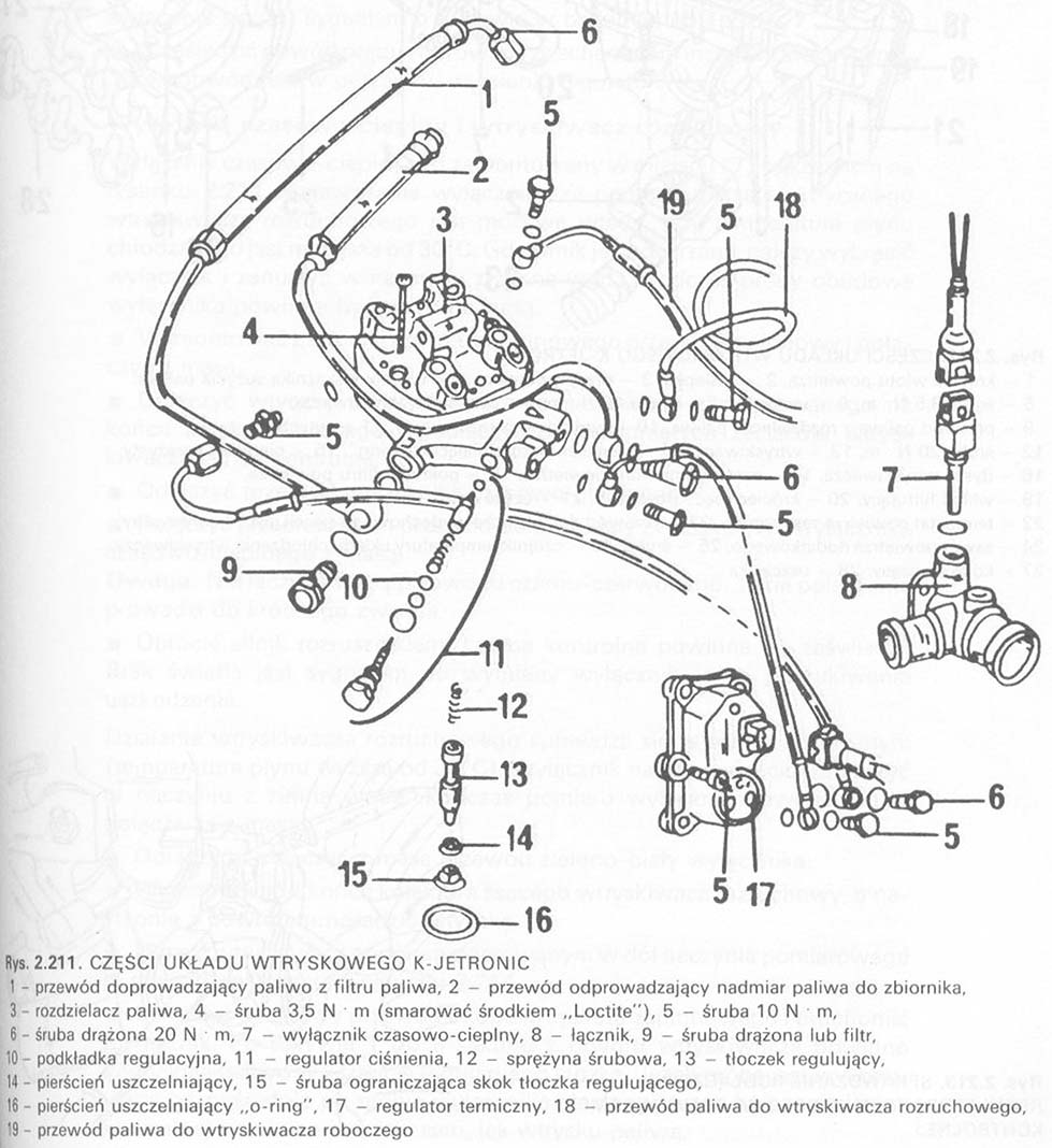
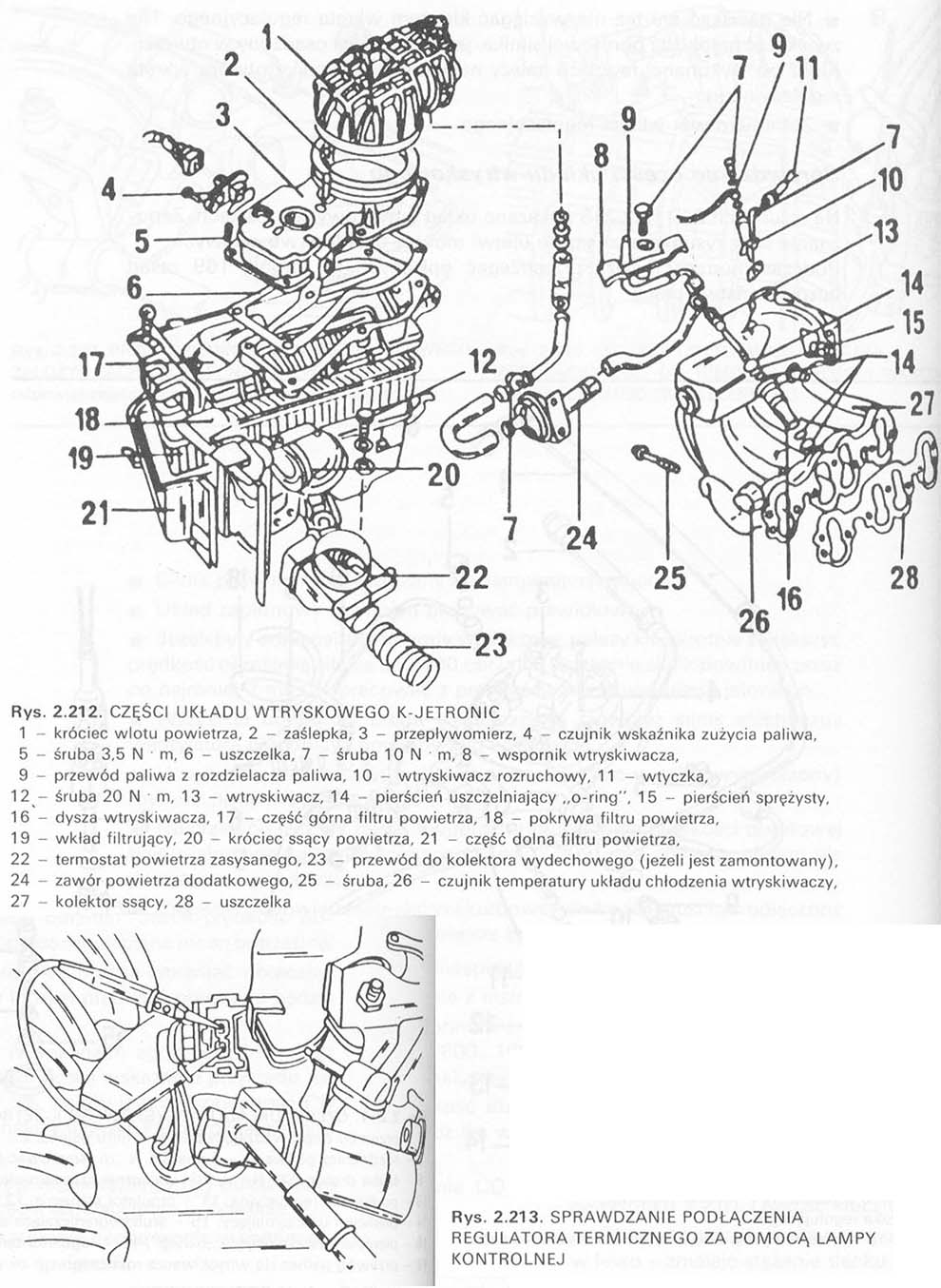
In the drawings 2.211 …2.21 3 the injection system is shown in parts. Reading the drawings will greatly facilitate the assembly of injection systems. During assembly, work safety rules must be followed.
Fuel pump
If the voltage at the battery terminals is correct, and the pump is not running, Please check the fuse number ,,13″ pump circuit. If the fuse is not damaged, check the operation of the pump. Operate the starter for a short time with the ignition cable removed from the distributor cap and a short to ground. The operation of the pump is clearly audible. Special tools are required to thoroughly inspect the pump. Have the pump examined by a specialist repair shop.
Thermal regulator
■ Remove center ignition wire from dome on igniter and short to ground.
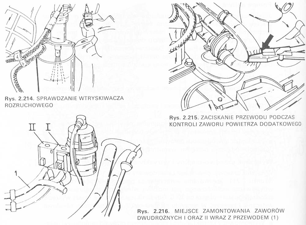
■ Disconnect the cable from the controller and connect the indicator light as shown in the picture 2.213.
■ Actuate the starter. The indicator lamp should light up; non-glowing is a signal about a break in the tested circuit.
■ Trace the circuit and compare it with the wiring diagram. If the circuit is okay, replace the regulator.
Timer and heat switch and starting injector.
The time / heat switch is installed in place (7) shown in the figure 2.211. The switch can then be checked with the electrical connector of the starter injector, when the coolant temperature is less than 30 C. When the engine is warm, unscrew the switch and immerse it in a vessel with cold water. During the test, the switch housing should be shorted to ground.
■ Remove the ignition cable from the bonnet and ground it.
■ Disconnect the plug from the starter injector mounted at the end of the intake manifold and connect a pilot lamp to the exposed terminals of the injector.
■ Disconnect the wire for the heat switch.
■ Use the extension cable to connect the green and white wire to the clamp ,,W ”ground thermal timer.
Caution. Do not connect the black and red wire with ground. This connection leads to a short circuit.
■ Turn the engine over with the starter. The indicator lamp should light up. Lack of light is a signal to replace the switch or look for damage.
The operation of the starter injector is checked when the engine is warm (fluid temperature higher than 30 C). The switch should be unscrewed and immersed in a vessel with cold water. The switch should be connected to the ground during the measurement.
■ Disconnect and ground the green / white wire of the switch.
■ Remove the starter injector from the end of the intake manifold, then put the plug back on.
■ Place the injector with the opening facing down the measuring vessel as shown in the picture 2.214.
■ Disconnect the center wire from the dome of the igniter and actuate the starter. After 1 do 8 seconds, the fuel should spray out in the shape of a regular cone from the injector bore. If the test is performed immediately after the thermal switch test, the lighting time of the control lamp should be the same, like fuel injection.
■ Dry the surface of the injector and observe it, do over at least 1 minutes, no drops of fuel flow out of the injector. Otherwise, replace the injector.
Auxiliary air valve
Auxiliary air valve (24) is in the position shown in the figure 2.212. The current flow to the valve can be checked with a control lamp.
■ Remove center high voltage wire from dome on igniter and short to ground.
■ Remove the plug from the valve socket and connect the socket wires with the control lamp.
■ Crank the engine with the starter – the control lamp should light up. Lack of light is a signal to replace the valve or remove the damage.
The operation of the valve must be checked, when the engine temperature is below 30 C.
■ Disconnect the auxiliary air valve tubing.
■ Connect the tachometer according to the instructions in the tachometer manufacturer's operating manual (then turn off the ignition).
■ Start the engine and establish idle speed.
■ Clamp the connecting hose from the auxiliary air valve to the suction port as shown in the figure 2.215. After clamping the hose, the engine speed should decrease.
■ Carry out a similar test with the engine warm. Before trying, put the plug with wires on the valve. Engine speed, after crimping the auxiliary air line, should not change. If the rotational speed changes, the valve must be replaced.
Two-way valves I and II
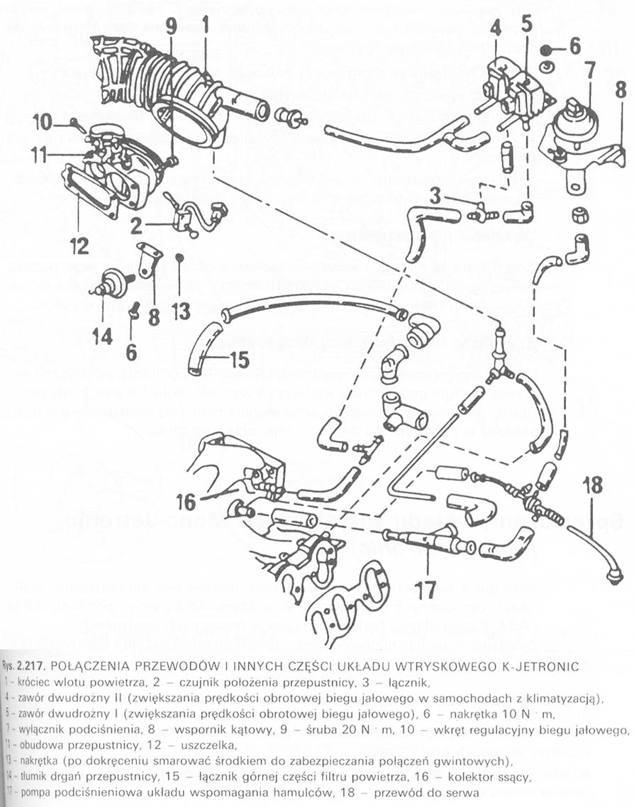
The location of both valves is shown in the figure 2.217. The valves increase the idle speed, when it goes below 700 RPM (valve I) or the air conditioning unit switches on (in cars with air conditioning). Checking the operation of the valves is relatively easy.
Valve I is checked in the following sequence.
■ Disconnect the air conditioning unit. Start the engine and establish the idle speed.
■ Switch off all electric consumers.
■ Screw in the speed adjusting screw yes, that the rotational speed is 700 RPM. The valve should open at this speed, and the engine speed should increase.
■ Clamp the cable with the clamp (1, lynx. 2.216). The engine speed must drop immediately.
■ Increase the engine speed to 900 RPM – the cord should remain clamped.
■ Remove the clamp from the hose. The engine speed should increase. When the engine speed reaches the value of 1050 RPM, the valve should close, and the speed should drop to the previously recommended value.
When checking valve II, perform the following steps.
■ Switch off the air conditioning unit.
■ Start engine and establish idle speed.
■ Clamp the cable (1). The engine speed should not change.
■ Switch on the air conditioning unit and repeat the test. The engine speed should slow down with the hose pinched.
Change the air filter
The parts of the air filter and other units mounted near it are shown in the illustration 2.212. The filter element of the filter should be replaced every 30 000 km. Before replacing, all parts should be thoroughly cleaned.
Throttle cable adjustment
Set the throttle control cable so, so that the play between the throttle lever rotation stopper and the lever is approx 1,0 mm, when the gas pedal” is pushed in all the way. The setting is changed by inserting the snap ring in another groove of the cable armor at the bracket.


